

The ultimate way to prove that a program is working adequately is to run it on an hardware evaluation board instead of using a software simulator. For this task we will redirect the value of an 8 bit counter to a set of LEDs on a chosen evaluation board. For this tutorial we will use the Keil MCBSTM32 evaluation board.
To get the best out of this tutorial you may decide to download the following support files. In exchange, we will ask you to enter some personal details. To read about how we use your details, click here. On the registration form, you will be asked whether you want us to send you further information concerning other Doulos products and services in the subject area concerned.
Download the files for this tutorial »
Download the required software »
Background Information
A file must be included inside an existing main.c file. This file will define an initialization function for some of the I/Os. It can be found at: \intro\session1\src\gpio.h. Most importantly, this file in turn, includes the stm32f10x.h header.
This inclusion is a CMSIS requirement, and is used to define the peripherals for the actual device. In short, this file represents the CMSIS ‘Device Peripherial Access Layer’ header file and contains all the peripherial registers’ definiton, bits definition and memory mapping for the stm32f10x device.
The file will use several other include files to define the peripherals of the actual device notably, the CMSIS ‘Core Peripherial Access Layer’ (core_cm3.h). This can be observed after the first compilation run, by looking at the main.c file dependencies, inside the project window.
In order to drive the LEDs on the evaluation board we will have to drive values on their respective ‘General Purpose I/O’ (GPIOB). The stm32f10x.h file defines the macro GPIOB as:
#define GPIOB ((GPIO_TypeDef *) GPIOB_BASE)
With GPIO_TypeDef declared as a C structure defining the relative position of the GPIO internal registers such as:
typedef struct
{
  __IO uint32_t CRL;
  __IO uint32_t CRH;
  __IO uint32_t IDR;
  __IO uint32_t ODR;
  __IO uint32_t BSRR;
  __IO uint32_t BRR;
  __IO uint32_t LCKR;
} GPIO_TypeDef;
As a result accessing the GPIOB register is simple:
GPIOB->ODR = 0xSome_32_bit_value; // Writes to the Output Data Register
Actions
- Invoke μVision and navigate to the \intro\session1 directory: File > Open.
- Open the provided project file called session1.uproj.
- Ensure that project session1 is active (highlighted). Otherwise right-click the project name and select: Set as Active Project.
- Select Project > Options and move to the C/C++ tab. Inside the Define entry box, enter the value: STM32F10X_MD.
Inside the main.c file, we call the GPIOB initialization subroutine ( GPIOB_init() ). This function can be found inside the gpio.h file. Furthermore we add inside the main() function the following statement to drive the LEDs with the value of the variable i.
#include
#include "gpio.h"

int main(void) {
  int j = 0;
  unsigned char i =0;

  GPIOB_init(); /* Call initialization subroutine for GPIOB */

  while (1) {
    j++;
    if (j==1000000) {
      j = 0;
      if (i==0xFFFF) i = 0;
      printf("Value of i: %d\n", i);

      /* LEDs located at GPIOB[8-15] */
      GPIOB->ODR = (GPIOB->ODR & 0xFFFF00FF) | (i << 8);
      i++;
    }
  }
}
Note: The ODR (Output Data Register) register is used to set/reset the values driving the LEDs. On the MCBSTM32 demo board, the LEDs[0-7] are connected to GPIOB[8-15].
- Compile the project.
- Connect the evaluation board to the PC if it's not already connected.
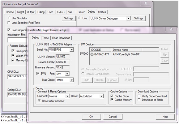
- Go to Project > Options for target Session1 In the Debug tab, set the options as shown in the following picture.
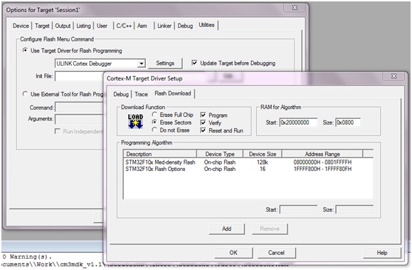
- Inside the Utilities tab, set the remaining options as shown in the next picture.
- Download the binary file onto the flash by selecting: Flash > Download. Once the program has been downloaded inside the device, you may have to press reset to start the proper execution.
Having downloaded the program onto the device you can decide to run an interactive debug to examine the initialization stage of the program (SystemInit). To do this, select: Debug > Start/Stop Debug Session and perform a step by step execution.
This concludes Programming a MCBSTM32 Evaluation Board, the final tutorial of this series.