

KnowHow
Free Technical Resources
This tutorial explains the split_transactors feature of the Code Generator.
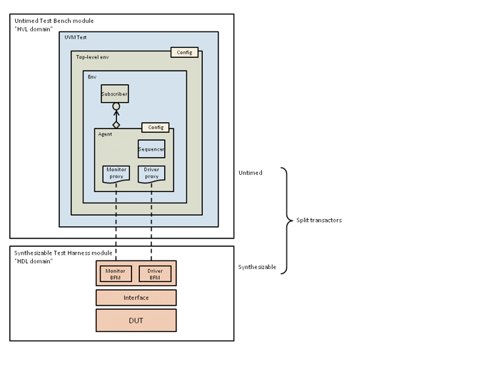
When running a UVM simulation on an accelerator or emulator box, the UVM testbench running on the host computer can easily become a bottleneck because it is running much slower than the DUT. The idea is to move as much of the UVM testbench code as possible onto the accelerator or emulator box in order to speed up simulation. This means splitting each transactor (UVM driver or monitor) into two parts, a lightweight proxy or wrapper that continues to run on the host, and a synthesizable part (BFM or Bus-Functional Model) that runs on the box and wiggles the pins of the DUT. In order to achieve this, the code has to be structured into two separate domains:
The solutions provided by most EDA tool vendors make use of the SCE-MI standard for communication between the host computer and the accelerator or emulator box. SCE-MI allows the communication between the host computer and the box to occur at the transaction level. The tool vendor may be able to synthesize selected parts of the UVM testbench straight onto the box (including generation of the necessary SCE-MI interfaces), or you may need to do some manual work to transform your UVM code into a form suitable for SCE-MI communication and for synthesis. This step will depend on the capabilities of your tool vendor and is beyond the scope of the Easier UVM Code Generator and this tutorial.
The files for this example are in the directory ./minimal_split_txor of the Easier UVM Code Generator release. We will describe the necessary user-defined code fragments and the generated code below.
You tell the Code Generator to create split transactors by including the setting split_transactors = yes in the common template file:
Filename common.tpl
dut_top = mydut
split_transactors = yes
top_default_seq_count = 5
This setting infers the setting dual_top = yes, which means that the Code Generater will create two separate top-level modules, one untimed and one synthesizable, although whether the test harness actually is synthesizable will depend on the user-defined code fragments you include.
The synthesizable test harness contains code to generate the clock and the reset and code to instantiate the BFM, the pin-level interface, and the DUT. This code is not necessarily synthesizable in its entirety using regular RTL synthesis tools, but there do exist dedicated synthesis tools that target accelerator and emulator boxes that could handle it. The only difference between the test harness below and a test harness without split transactors is that the test harness below instantiates the bus_bfm interface, which contains the synthesizable parts of the transactors for the bus agent:
module top_hdl_th;
  ...
  logic clock = 0;
  logic reset;

  always #10 clock = ~clock;

  initial
  begin
    reset = 0;
    #75 reset = 1;
  end

  assign bus_if_0.clk = clock;

  // Pin-level interfaces connected to DUT
  bus_if   bus_if_0 ();

  // BFM interfaces that communicate with proxy transactors in UVM environment
  bus_bfm  bus_bfm_0 (bus_if_0);

  mydut uut (
    .bus_clk (bus_if_0.clk),
    .bus_cmd (bus_if_0.cmd),
    .bus_addr(bus_if_0.addr),
    .bus_data(bus_if_0.data)
  );

endmodule
The untimed testbench instantiates the UVM environment:
module top_untimed_tb;
  ...
  top_config env_config;

  initial
  begin
    env_config = new("env_config");
    if ( !env_config.randomize() )
      `uvm_error("top_untimed_tb", "Failed to randomize configuration object" )

    env_config.bus_vif             = top_hdl_th.bus_bfm_0;
    env_config.is_active_bus       = UVM_ACTIVE;
    env_config.checks_enable_bus   = 1;
    env_config.coverage_enable_bus = 1;

    uvm_config_db #(top_config)::set(null, "uvm_test_top.m_env", "config", env_config);

    run_test();
  end

endmodule
The important point to note about the untimed testbench (apart from the fact that it must be untimed) is that the virtual interface (within the top-level configuration object) is set to point to the BFM interface within the test harness top_hdl_th.bus_bfm_0. This is a full hierarchical reference to the interface instance bus_bfm_0 within the top-level module top_hdl_th. When the UVM driver and monitor proxies communicate with the code outside the class-based verification environment using their local virtual interface variables, they will actually be communicating with the BFM in the synthesizable test harness.
The Easier UVM Code Generator interface template file contains settings to include the various user-defined code fragments necessary to define the UVM driver, which is just a proxy or wrapper for the full driver (transactor), most of which is implemented on the HDL side in the synthesizable BFM:
Filename bus.tpl
...
trans_inc_before_class       = bus_trans_inc_before_class.sv    inline
driver_inc_inside_class      = bus_driver_inc_inside_class.sv   inline
driver_inc_after_class       = bus_driver_inc_after_class.sv    inline
...
Filename bus_trans_inc_before_class.sv
typedef struct packed {
  bit cmd;
  byte addr;
  byte data;
} bus_tx_s;
Filename bus_driver_inc_inside_class.svv
extern task run_phase(uvm_phase phase);
Filename bus_driver_inc_after_class.sv
task bus_driver::run_phase(uvm_phase phase);
  forever
  begin
    bus_tx_s req_s;
    seq_item_port.get_next_item(req);

    // Copy fields to packed struct
    req_s.cmd  = req.cmd;
    req_s.addr = req.addr;
    req_s.data = req.data;

    // Call HDL-side transactor
    vif.drive(req_s);

    seq_item_port.item_done();
  end
endtask : run_phase
The run_phase method of the UVM driver gets one transaction at a time from the sequencer and calls the drive function of the BFM through its virtual interface. Because the "interface" between the HVL and HDL domains has to map onto the SCE-MI interface of the accelerator/emulator it cannot pass arbitrary data types, such as handles to objects, but is restricted to synthesizable data types. One reasonable approach, the one shown here, is to copy the fields of the transaction object into a single packed struct, which is then passed as an argument to the drive task (and ultimately passed across the SCE-MI interface from the host to the emulator). The typedef for the packed struct can be included before the uvm_sequence_item class (setting trans_inc_before_class), thus making it available to all the classes associated with the particular agent (see FAQ).
Again, the significant point about the code above is that it is just a proxy or wrapper for the real work of the driver, which is actually done by code (within the drive task) that is synthesized onto the emulator box.
The synthesizable parts of the drivers and monitors must be provided as user-defined code fragments and included within the BFM:
Filename bus.tpl
...
agent_inc_inside_bfm = bus_inc_inside_bfm.sv  inline
...
After code generation, the resultant BFM will be as follows:
interface bus_bfm(bus_if if_port);

  import bus_pkg::*;

  // Start of inlined include file generated_tb/tb/include/bus_inc_inside_bfm.sv
  // HDL-side synthesizable transactors

  task drive(bus_tx_s req_s);
    @(posedge if_port.clk);
    if_port.cmd  <= req_s.cmd;
    if_port.addr <= req_s.addr;
    if_port.data <= req_s.data;
  endtask
  ...
  // End of inlined include file

endinterface : bus_bfm
This particular driver is trivial; an actual driver would have to do whatever is needed to implement the particular protocol being used. The code must comply with whatever rules are imposed by the tool vendor to make it synthesizable for the purposes of acceleration/emulation. These rules are usually less restrictive than those of RTL synthesis. For example, many vendors support an implicit FSM style with multiple @(posedge clock) statements within a single procedure.
Note that the BFM is an interface that has an interface port (if_port) which will refer to the pin-level interface after both interfaces have been instantiated. Any user-defined code fragments will need to refer to the pin-level interface using this interface port.
The code above shows the downstream route by which a driver proxy on the host passes information across to a transactor implemented on the box. It is possible to implement the monitor in exactly the same way, that is, a monitor proxy on the host can make a time-consuming task call to get information from a transactor on the box, for example:
task bus_monitor::run_phase(uvm_phase phase);
  forever
  begin
    bus_tx_s rsp_s;
    bus_tx tx;

    vif.get_next_transaction_from_emulator(rsp_s);

    tx = bus_tx::type_id::create("tx");
    tx.cmd  = rsp_s.cmd;
    tx.addr = rsp_s.addr;
    tx.data = rsp_s.data;
    analysis_port.write(tx);
  end
endtask : run_phase
The downside of this approach is that it is an inefficient way to pass information over the communication link between the host and the emulator. It is more efficient to have the emulator push information to the host only when it is ready to do so. In this way both simulator and emulator can continue to execute in parallel: the emulator does not need to stall while waiting for the testbench to catch up. This approach is enabled by first setting up a back pointer from the BFM to the UVM monitor proxy object, as follows:
interface bus_bfm(bus_if if_port);

  import bus_pkg::*;

  // Start of inlined include file generated_tb/tb/include/bus_inc_inside_bfm.sv
  ...
  import bus_pkg::bus_monitor;
  bus_monitor proxy_back_ptr;

  task run;
    forever
    begin
      bus_tx_s req_s;
      @(posedge if_port.clk);
      req_s.cmd  = if_port.cmd;
      req_s.addr = if_port.addr;
      req_s.data = if_port.data;
      proxy_back_ptr.write(req_s);
    end
  endtask
  // End of inlined include file

endinterface : bus_bfm
The synthesized BFM on the box now initiates monitor transactions when it is ready to do so. The write method is implemented within the UVM monitor proxy in the usual way:
// Start of inlined include file generated_tb/tb/include/bus_monitor_inc_after_class.sv
task bus_monitor::run_phase(uvm_phase phase);
  vif.proxy_back_ptr = this;
  vif.run();
endtask

function void bus_monitor::write(bus_tx_s req_s);
  bus_tx tx;
  tx = bus_tx::type_id::create("tx");
  tx.cmd  = req_s.cmd;
  tx.addr = req_s.addr;
  tx.data = req_s.data;
  analysis_port.write(tx);
endfunction
// End of inlined include file
Note that the monitor proxy assigns the back-pointer and starts a process running on the box at the start of the UVM run phase. It then sits passively until the transactor on the box calls its write method, at which point it creates a new UVM transaction and sends it out through its analysis port.