
KnowHow
Free Technical Resources
On the page "Components and Port Maps", we looked at the VHDL used to describe the instantiation of components in an architecture. Instantiating components in VHDL enables us to create a design hierarchy, it's just like plugging chips into a PCB. In our case, the MUX2I is the PCB, the AOI gate and the inverter (INV) are two chips. But what about the sockets? Let's look into instantiating components in a little more detail.
Remember that the two component declarations (for INV and AOI) must match the corresponding entity declarations exactly with respect to the names, order and types of the ports. This is important because, as a hardware analogy, the component declaration is essentially a chip socket for the chip represented by the design entity - the entity declaration defines the pins of the chip.
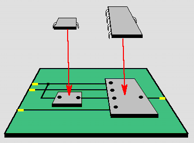
So, instantiation is essentially a VHDL term for soldering a chip socket into a PCB. Instantiation also assumes that the socket contains the chip referenced by the same name as it is plugged into the PCB. However, for our purposes, we can think of component instantiation as plugging a chip into a PCB, ignoring whether it's socketed or not.
component INV
  port (A: in STD_LOGIC;
  F: out STD_LOGIC);
  some more code
  ...
end component;
G1: INV
  port map (SEL,
  SELB
);
The concept of port mapping is little more than soldering the chip socket pins into the holes of the PCB. Thus in the case of our inverter, the F output pin of the INV chip is plugged into the F pin of the INV socket. The F pin of the INV socket is soldered to a PCB trace called SELB.
Similarly, instantiation of the AOI gate can be thought of as soldering the AOI socket into the MUX2I PCB. In this case, as an example, the SELB trace is soldered to the C pin of the AOI socket. By default, the AOI socket is assumed to be carrying an AOI chip.
architecture STRUCTURE of MUX2I is
...
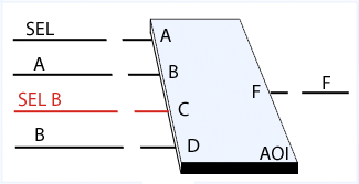
component AOI
port (A, B, C, D: in STD_LOGIC; -- 3rd item in list is C
F : out STD_LOGIC);
end component;
signal SELB: STD_LOGIC;
begin
...
G2: AOI port map (SEL, A, SELB, B, F); -- 3rd item in list is SELB
end;
Our current view of component instantiation assumes default binding. In default binding, the chip socket (component declaration) carries a chip (design entity) of the same name (say, AOI) as we've already seen. Now in the hardware world, there's no such limitation, sockets aren't chip specific. VHDL allows the designer the same freedom. The chip socket and the chip do not have to have the same name, but to implement this facility requires a configuration to bind the appropriate design entity to the component instantiation. We'll look at configurations shortly.
Your e-mail comments are welcome - send email
Copyright 1995-2016 Doulos