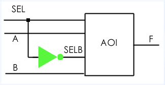
The example above shows the previously defined design entity AOI being used as a component within another, higher level design entity MUX2I, to create a design hierarchy with two levels. The design entity MUX2I also contains a second component, named INV. In order to write the VHDL for this circuit, we need to cover two new concepts: component instantiation (placing the INV and AOI inside another higher-level design, MUX2I) and port mapping (connecting up the two components to each other and to the primary ports of MUX2I). In VHDL, this is how we can model PCBs assembled from individual chips, for example.
The two component declarations (for INV and AOI) must match the corresponding entity declarations exactly with respect to the names, order and types of the ports. We've already seen enough of the AOI gate, let's see how closely the component and entity declarations match for the INV design entity.
| Entity | Component |
|---|---|
entity INV is port (A: in STD_LOGIC; F: out STD_LOGIC); end INV; |
component INV port (A: in STD_LOGIC; F: out STD_LOGIC); end component; |
The two component declarations (for INV and AOI) appear in the architecture declarative part (that's a VHDL technical term that means that the component declarations are coded before the begin).
library IEEE;
use IEEE.STD_LOGIC_1164.all;

entity MUX2I is
  port (SEL, A, B: in STD_LOGIC;
  F : out STD_LOGIC);
end;

architecture STRUCTURE of MUX2I is

component INV
  port (A: in STD_LOGIC;
  F: out STD_LOGIC);
end component;

component AOI
  port (A, B, C, D: in STD_LOGIC;
  F : out STD_LOGIC);
end component;

signal SELB: STD_LOGIC;

begin
  G1: INV port map (SEL, SELB);
  G2: AOI port map (SEL, A, SELB, B, F);
end;
The architecture STRUCTURE of MUX2I makes instances of INV and AOI through the component instantiations at the bottom of the architecture (labelled G1 and G2). The component names (INV and AOI) are references to design entities defined elsewhere. The instance labels (G1 and G2) identify two specific instances of the components, and are mandatory.
The ports in a component declaration must usually match the ports in the entity declaration one-for-one. The component declaration defines the names, order, mode and types of the ports to be used when the component is instanced in the architecture body. Instancing a component implies making a local copy of the corresponding design entity - a component is declared once within any architecture, but may be instanced any number of times. In this example, there is just one instance of the components AOI and INV.
Signals in an architecture are associated with ports on a component using a port map. In effect, a port map makes an electrical connection between “pieces of wire” in an architecture (signals) and pins on a component (ports). The same signal may be associated with several ports - this is the way to define interconnections between components.
In our MUX2I example, the signal SELB is associated with the F port of the INV instance and the C port of the AOI instance.
Your e-mail comments are welcome - send email
Copyright 1995-2016 Doulos